
Current location: ENGLISh > NEWS > Industry Trends >
How should the pipeline cleaning work of high viscosity pumps be carried out saf
time:2018-10-12 03:37:36 author:特种泵阀 click:636
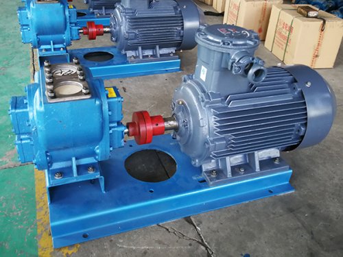
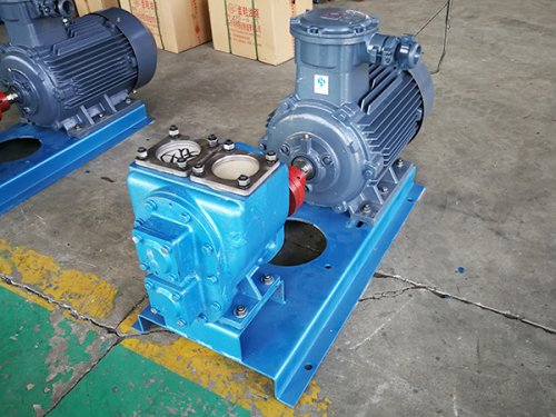
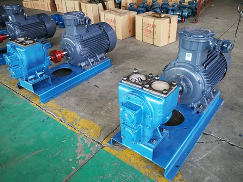
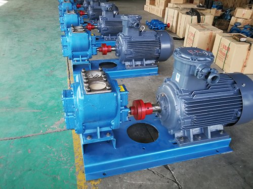
High viscosity pump is a new type of positive displacement pump developed according to the needs of industries such as petroleum, chemical, coatings, oils and fats, pharmaceuticals, dyes, and food. As this product can be made of different materials and structures, it is suitable for conveying media with different properties and viscosities. When conveying materials that are prone to crystallization, insulation jackets can be installed on the front cover and pump body, which are melted by steam insulation during operation. When viewed from the extended end of the main shaft towards the pump, it rotates clockwise. A high viscosity pump is a device used for transporting high viscosity liquids, and its application range is limited. Although domestic enterprises have produced many gear pumps suitable for transporting high viscosity liquids, there are still some problems in material selection, leakage and noise prevention due to inadequate testing methods. How to carry out pipeline cleaning work for high viscosity pumps is one of the comparative issues. The following is a specific introduction:
1. Pre operation inspection and preparation work for high viscosity pumps
Before implementing high viscosity pump cleaning operations, a cleaning plan should be developed based on the cleaning purpose, pipeline operating parameters, etc., and a suitable cleaning device should be selected. The cleaning plan serves as the basis for guiding the cleaning work, including cleaning operation steps, precautions, accident prediction, and handling methods. Estimate the operating speed of the cleaning device, inter station ball passing time, required ball pushing pressure difference, and other parameters based on the conditions of the high viscosity pump pipeline to help analyze and determine whether the ball passing operation is normal. The selected cleaning device is in the expected state for the intended purpose. For previously used cleaning tools, they can be reused without getting stuck in the pipeline. Measure the outer diameter of the sealing surface of the pipe cleaner, which should be greater than the inner diameter of the pipeline to achieve the desired sealing effect. Carefully inspect the sealing surface for any cuts, cracks, punctures, or other damages that may affect the normal operation of the pipe cleaner in the pipeline. The unconstrained diameter of the brush type pipe cleaner should also be measured to maintain close contact with the pipe wall throughout the entire operation process. When using a brush type cleaner with a core shaft, it is necessary to check whether the brush is corroded or damaged.
Take preventive measures to prevent the brush from being damaged in the high viscosity pump pipeline. Scattered bristles can damage valves, instruments, and other piping equipment. All components of the brush type pipe cleaner with a core shaft need to be carefully inspected for their firmness and condition. If it is a cleaning ball, fill it with water, exhaust the air, and press it to the specified interference amount. The tightness of the water injection port should be ensured. The continuous bolts of the cup clamp plate of the cup cleaner should be tightened appropriately and anti loosening measures should be taken. Before transmission, it is necessary to strictly inspect the continuous bolts and anti loosening parts of the signal transmitter and the cleaning device to prevent them from loosening and falling off during movement.
2. Distribution of high viscosity pump cleaning equipment
Before distributing the cleaning device, it should be confirmed that the isolation valve and bypass pipeline valve are in the closed state. For liquid pipelines, open the drain valve and open the exhaust valve to allow air to replace the liquid flow. For gas pipelines, open the exhaust valve to reduce the pressure of the launcher to atmospheric pressure. When the launcher is emptied (without residual pressure), keep the exhaust valve and drain valve open, and open the blind plate. When installing the pipe cleaner, the cleaner is in close contact with the reducer, which is located between the straight section and the nominal diameter section of the launcher. Clean the sealing surface of the blind plate and other sealing surfaces, lubricate them if necessary, then close the blind plate and fix it firmly. Close the drain valve, gradually open the bypass pipeline valve and exhaust through the exhaust valve, slowly fill the bypass pipeline. After the filling process is completed, close the exhaust valve to increase the pressure to equilibrium with the pressure at the other end of the isolation valve. Open the isolation valve and prepare the pipe cleaner for distribution. Reduce the opening of the main valve, increase the flow of the bypass pipeline and the pipeline behind the cleaner. Continue to close the mainline valve until the pig leaves the bypass pipeline and enters the mainline, which can be determined by the pig signal indication. After the cleaning device leaves the bypass pipeline and enters the main line, open the main line valve, close the isolation valve and the bypass pipeline valve. The distribution of cleaning equipment has ended. When the pig runs to a distance of 200-1000m from the receiving station, it should issue a warning to the receiving station for the start of the receiving operation.
3. High viscosity pump cleaner receiver
When receiving the pig, be careful that the receiving cylinder has been pressurized. Open the bypass valve. Open the isolation valve and close the main valve appropriately. Monitor the pig signal to determine if the pig has arrived. After arrival, close the isolation valve and bypass valve. Open the drain valve and exhaust valve. Check the pressure gauge on the receiving cylinder and release the pressure inside the cylinder. Open the blind flange and remove the cleaning device from the receiving cylinder to clean it. Clean the sealing surface of the blind plate and other sealing surfaces, lubricate them if necessary, then close the blind plate and fix it firmly. Restore the receiving cylinder to its original state.
4. Handling of abnormal situations during the cleaning process of high viscosity pump pipelines
The pour point is a flow characteristic parameter of oil that is closely related to the shutdown time of high viscosity pump hot oil pipelines. The inlet temperature of the heating station is basically determined based on the pour point of the oil. For the same temperature at the start of shutdown, the lower the condensation point, the longer the shutdown time. To investigate its specific impact on the shutdown time, the pipeline shutdown time at different condensation points was calculated.
In addition, before starting the operation of the high viscosity pump, fill the housing of the gear pump with the liquid to be conveyed for easy start-up. If the ambient temperature is below freezing point, hot steam should be introduced into the pump in advance for preheating treatment before starting the gear pump. The rotation direction of high viscosity pumps should match the inlet and outlet ports. If the gear pump is running for the first time or has been idle for a long time before use, it can be run for about an hour under no-load or low load conditions. If abnormal temperature rise, leakage, vibration, and noise are detected in advance during the running in phase, the machine should be stopped for inspection. The support or flange of the high viscosity pump and its driving motor should use a common installation foundation, and the foundation, flange or support should have sufficient rigidity to reduce the vibration and noise generated during the operation of the gear pump. The electric motor and gear pump must be connected with an elastic coupling, with a coaxiality of less than 0.1 millimeters and a tilt angle of no more than 1 degree. Do not use a hammer to strike the coupling during installation to avoid damaging the gears and other parts of the gear pump. If driven by pulleys, sprockets, etc., a bracket support should be installed to prevent the active gear bearings from being subjected to radial forces. When tightening the foundation screws of gear pumps and motors, the screws should be evenly stressed and connected. When rotating the coupling by hand, you should feel that the gear pump can rotate easily without any abnormal phenomena such as clamping before piping can be installed.