
Current location: ENGLISh > NEWS > Company News >
Simple analysis of the loading and unloading process and fault causes of gear pu
time:2018-11-11 04:19:03 author:特种泵阀 click:437
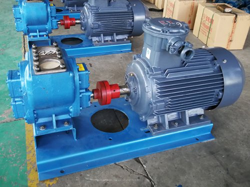
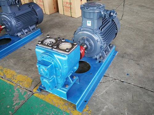
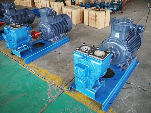
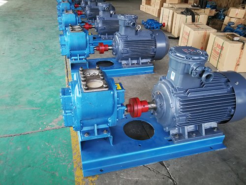
After the gear pump is ordered and delivered, it should be installed on the machine equipment. Before assembly, the appearance of the ordered pump and motor should be checked for any hard damage. Any damage caused during transportation is the responsibility of the seller. Check if the dust covers on the inlet and outlet of the pump body are intact. If there is any damage, check if nothing has entered the pump body and clean it before use. The installation position of the pump should be dry and well lit for easy disassembly and maintenance. The pump and motor are installed on the base plate and fastened with bolts to prevent deformation of the base plate. The inlet and outlet diameter of the pump should not be smaller than the inlet and outlet diameter of the pump. The inlet pipe should have a slightly larger diameter, and the shorter the inlet pipe, the better. The elbow should have a larger bending radius. The oil suction outlet of the inlet pipe should be cut at a 45 degree angle. The pump shaft and motor shaft should be installed concentric. If the concentricity is not good, the pump may wear out during rotation.
The models of gear pumps generally include YCB gear pumps, NYP rotor pumps, KCB gear pumps and other conventional products. Generally speaking, the performance indicators and size parameters of this pump are judged by the first letter model. Here is an example of a gear oil pump such as YCB4/0.6, whose working parameters are: the flow rate of this gear pump is 4m3/h, and the working pressure is 0.6MPA. As long as it meets this working environment, it can be used. There are also several common gear oil pumps, including KCB gear pumps, which represent gear pumps with valves, KCB200, The flow rate of this gear pump is 200l/min. In YCB gear pumps, YCB represents the circular arc gear pump, which refers to the structural characteristics of this type of gear pump. These are only judged on the surface, and the specific parameters still depend on the instructions of the gear oil pump and the information on the warranty card.
The specific process for assembling and disassembling gear pumps is as follows:
1. Clean all the components to be installed.
2. Install a mechanical seal on the motor spindle, and add a small amount of clean turbine oil or No. 20 engine oil to the surface where the dynamic and static rings of the mechanical seal match.
3. Install the impeller and tighten it with the impeller nut.
4. Install "; 0" O-ring, tighten the pump body and motor end cover with bolts. Pay attention to maintaining a clearance of 2+0.5 millimeters between the impeller front cover plate and the pump body, as well as a running clearance between the impeller outer ring and the pump body.
5. The disassembly sequence is opposite to this.
The installation and usage of gear pumps are as follows:
1. Connect the flanges at both ends of the pump body and the pipeline flange with rubber washers and bolts, and the installation is completed. For the convenience of use and maintenance, a regulating valve should be installed on both the inlet and outlet pipelines of the pump.
2. Open the regulating valve to allow water to enter the pump to keep the sealed chamber filled with liquid (otherwise it will damage the seal), and close the outlet valve.
3. Connect the power and jog to confirm the correct direction.
4. After the steering is confirmed, start and operate the pump.
5. Adjust the opening of the outlet valve to operate the pump near the point, based on the rated flow rate and head of the pump. For this, a pressure gauge can be installed near the outlet flange. Attention: This pump is strictly prohibited from running without water to avoid damaging the seals.
The troubleshooting methods for gear pump faults are as follows:
1. The insulation gear pump does not produce water and the water injected into the insulation pump is insufficient, the rotation direction is incorrect, and the impeller flow channel is blocked.
Inject water into the insulation pump again, pass it through the impeller channel, and adjust the rotation direction.
2. Insufficient flow of insulation gear pump, partial blockage of insulation pump, low rotation speed, total head higher than the rated value of the pump, and damaged impeller.
Clean the insulation pump and pipes, replace the impeller, increase the shaft speed of the insulation pump, and adjust the outlet valve.
3. Insufficient outlet pressure, air in the liquid, low speed, damaged impeller, and excessively wide outlet valve opening.
Remove air from the liquid, increase the pump speed, replace the impeller, and adjust the outlet valve.
4. Gear pumps consume excessive power (motor overheating) due to mechanical defects such as small running clearance, bent motor shaft, loose bolts, etc. The pump operates at too high a flow rate, i.e. the pump operates far below the rated head.
Check and adjust the mechanical part in a timely manner, adjust the outlet valve to make the pump work near the rated flow and head.
5. The vibration pipeline system of the insulation gear pump is not well supported, and the impeller is partially blocked, causing imbalance, resulting in cavitation and air in the liquid.
Inspect the pump support department, tighten the nut, balance the impeller, and eliminate air leakage.
6. The mechanical seal of the insulation pump is damaged due to water leakage, the O-ring is damaged, and the pump body is leaking water. Replace the mechanical seal and O-ring, and weld the leaking part of the pump body.
7. The insulation gear pump produces excessive noise and the bearings are overheated and lack oil, resulting in a heavy load on the insulation pump. Add oil to the bearing and eliminate it according to the above method.