
Current location: ENGLISh > NEWS > Industry Trends >
A brief introduction to the needle roller components and fluid types of gear pum
time:2018-12-01 04:34:58 author:特种泵阀 click:694
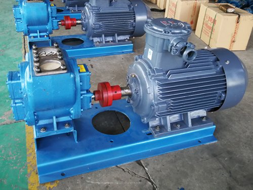
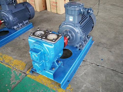
Gear pump is a rotary pump that relies on the change and movement of the working volume formed between the pump cylinder and the meshing gear to transport liquid or increase its pressure. Two enclosed spaces are composed of two gears, a pump body, and front and rear covers. When the gears rotate, the volume of the space on the disengagement side of the gears increases from small to large, forming a vacuum that sucks in the liquid. The volume of the space on the meshing side of the gears decreases from large to small, and the liquid is squeezed into the pipeline. The suction chamber and the discharge chamber are separated by the meshing line of two gears. The pressure at the discharge port of a gear pump depends on the magnitude of the resistance at the pump outlet.
The end cover of the gear pump is made of cast iron. If there is wear, it can be lightly ground and leveled on a flat plate. If the wear is severe, it should be ground and leveled on a surface grinder. The flat contact between the end cap and the pump body after grinding should not be less than 85%. The flatness tolerance, perpendicularity tolerance of the end face to the hole centerline, parallelism tolerance of the two end faces, and parallelism tolerance of the two axis hole centerlines are all O.Olmm. The surface roughness Ra after grinding should not exceed 1.25 μ m.
After repairing the parts in the gear pump, the bearing needle rollers should be replaced. The requirements for needle rolling are: the dimensional error of all needle rolling diameters should not exceed 0.003mm, the allowable length deviation is 0.1mm, and the clearance with the shaft should be around O.Olmm; When assembling the rolling needles, they should be filled into the bearing housing according to the required quantity, and the rolling needles should be arranged parallel to each other.
Regarding the issue of wear and maintenance of gear pumps, the above content is shared with everyone. In addition, it should be noted that besides wear and maintenance, what we need to do for gear pumps is actually daily standardized use and maintenance, which can reduce the degree of wear of gear pumps and thus improve their operation.
Friends familiar with gear pump products know that gear pumps, also known as positive displacement devices, are like pistons in a cylinder. When one tooth enters the fluid space of another tooth, the liquid is mechanically squeezed out. Due to the fact that liquids cannot be compressed, liquids and teeth cannot occupy a unified space at the same time, and as a result, liquids are not compressed. Due to the continuous meshing of teeth, this phenomenon occurs continuously, thus providing a continuous displacement at the pump outlet. The displacement is the same for each rotation of the pump. As the drive shaft rotates continuously, the pump also continuously squeezes out the fluid. The flow rate of a pump is directly related to its rotational speed.
The principle of gear pump in actual operation is relatively simple, that is, its fundamental situation is that two gears of the same size mesh and rotate with each other in a common housing, and the interior of this housing is similar; 8” Character shape, two gears are installed inside, and the outer diameter and sides of the gears are shared with the housing. The material from the extruder enters the center of two gears at the suction port and fills this space. It moves along the shell with the rotation of the teeth and is then squeezed out when the two teeth mesh.
In fact, there is a small amount of fluid loss inside the gear pump, which makes the pump's operating power close to full. As these fluids are used to lubricate the bearings and both sides of the gear, and the pump body is also approximately gapless, it is not possible to completely displace the fluid from the outlet, resulting in a small amount of fluid loss. However, the pump can still operate, and for most extruded materials, it can still achieve compliance with~.
This pump will not be greatly affected in dealing with fluids with viscosity or density changes during the process. If there is a damper, such as placing a filter or a limiter on the displacement port side, the pump will push the fluid through them. If this damper changes in the process, that is, if the filter becomes dirty, clogged, or the back pressure of the limiter increases, the pump will still be connected to a constant flow until it reaches the weaker component of the device's machine (usually equipped with a torque limiter).
The speed of a gear pump is actually limited, depending on the process fluid. If oil is being transported, the pump can rotate at a high speed. However, when the fluid is a high viscosity polymer melt, this limit will be significantly reduced.
It is very important to push high viscosity fluid into the two tooth space on the suction side. If this space is not filled, the pump cannot displace the correct flow rate, so PV value (pressure flow rate) is also another limiting factor and a process variable. Due to these limitations, gear pump manufacturers will provide a range of products with varying specifications and displacements (the amount displaced per revolution). These pumps will be combined with detailed application processes to achieve a balance between system capability and cost.
Having a thorough understanding of the working principle of gear pump products helps us to operate them in a standardized manner in practical applications. Once a gear pump product malfunctions, we can detect it at an early stage and then use our accumulated knowledge about the working principle of gear pumps to troubleshoot the problem. This can buy valuable time for the maintenance of gear pumps and reduce losses caused by machine failures to a certain extent.