
Current location:ENGLISh > PRODUCT > Light and heavy fuel booster pump >
Boosting fuel pump
15833379552
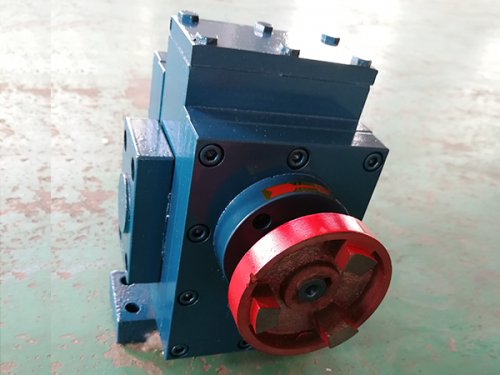
Boosting fuel pump is a volumetric fuel boosting and conveying component for industrial combustion systems, which is compatible with low viscosity diesel and medium high viscosity fuel oil transportation. It is divided into two types: room temperature basic type and jacket insulation type. It is matched with asphalt mixing stations, industrial boilers, heating furnaces, and combustion equipment burners for fuel supply and boosting systems. It can also be used for medium transfer between fuel storage tanks and fuel pre-treatment and conveying processes. The equipment supports 24/7 continuous pressurized fuel supply and is also suitable for intermittent fuel supply conditions with periodic start stop cycles in production lines.
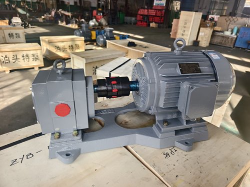
The entire unit consists of a pump body, front and rear pump covers, heat-treated alloy master and slave gears, quenched and tempered transmission shaft, floating thrust plate, shaft end sealing component, and built-in reflux valve to form a conveying unit. The gears have undergone chemical treatment, are resistant to erosion, and can withstand a small amount of gum impurities inside the fuel; A multi-channel axial force balance flow channel is installed inside the cavity to counteract the unidirectional axial thrust generated by the gear under pressure boosting conditions. The thrust plate is worn on one side, and the vibration is smooth during long-term continuous operation. The internal moving parts rely on fuel self lubrication, without the need for additional independent lubrication pipelines, simplifying the on-site pipeline layout. The insulated pump body and pump cover are equipped with a surrounding insulation layer, which can be supplied with steam and heat transfer oil to avoid gear jamming caused by low-temperature solidification of heavy oil; Some models are equipped with a gap adjustment mechanism, which can restore the boosting performance without disassembling the entire machine after pressure attenuation.
After the device is connected to the driving power, the motor drives the gears to rotate synchronously through the elastic coupling. The volume of the cavity on the side where the gears disengage continuously expands to form negative pressure. The fuel inside the storage tank is filled into the gap between the gear teeth through the widened smooth oil inlet channel. As the gears continue to rotate, the grooves carry the medium and transport it to the oil pressure area. The gears bite into the compression chamber volume, and the fuel forms a stable pressure and is transported to the burner pipeline. The suction, transportation, pressurization, and discharge processes continue to circulate. The pump body has no dead corners in the flow channel, balancing the efficiency of light fuel circulation and the ability to transport high viscosity media. The flow pulsation is small, and the fuel supply pressure of the burner is stable, helping the fuel to fully atomize and burn.
The pump body is integrated with a built-in reflux valve, which provides short-term overload protection and preset opening pressure at the factory. When the outlet pipeline is blocked, the valve is closed, and the pressure inside the chamber exceeds the rated range, the valve automatically opens, and some medium flows back to the oil suction chamber to release high pressure, reducing the damage of pressure shock to the pump body, pipeline, and combustion nozzle. This structure is only used for emergency protection in case of sudden blockage and cannot be used as a voltage regulator for a long time. When voltage regulation is required, independent pressure regulating accessories can be installed on external pipelines to work together. The inner wall of the pump body has been smoothed to reduce the adhesion and accumulation of gum and carbon deposits, and to delay the flow attenuation caused by long-term operation. The equipment has basic self-priming ability and can work normally with a small amount of pre filled medium upon initial start-up.
The sealing matching can be selected based on the temperature of the medium and the viscosity of the oil, using packing seals or hard alloy mechanical seals. Select anti swelling sealing accessories for diesel transportation; Select sealing components for high-temperature heavy oil operating conditions. The sealing component tightly fits the gap between the transmission shaft and the pump cover, reducing fuel leakage while blocking dust and water vapor from entering the cavity, preventing impurities from scratching the gear teeth. The disassembly and assembly process of sealing accessories has been optimized, and maintenance does not require dismantling the entire machine. Only the outer pump cover can be removed to complete the replacement, shortening the downtime of the production line. Conventional seals are suitable for medium temperatures not exceeding 200 ℃, and special seals can be upgraded for long-term high-temperature conditions.
At the medium adaptation level, this turbocharged fuel pump is suitable for delivering fuel media that do not contain hard metal particles, long fiber impurities, and have lubricating properties. The medium's kinematic viscosity range is 5 to 1500mm ²/s, and it is suitable for industrial commonly used fuels such as light diesel, heavy diesel, and fuel oil. Cast iron models are suitable for clean diesel transportation; Steel casting insulation models prioritize the transportation of high viscosity heavy oil; Paired with motor units, it can meet the oil supply needs of mixing stations and chemical areas. The equipment is not suitable for conveying strongly corrosive and highly volatile media. Metal components in contact with the medium have undergone rust prevention treatment, making them suitable for industrial sites with high dust and large temperature fluctuations in the open air.
In terms of installation and matching, the horizontal base of the whole machine is reserved with standard foot holes, and the installation is stable on the ground. The inlet and outlet can be flexibly adjusted according to the direction of the pipeline, and the large-diameter interface reduces the flow resistance of the medium. Install an elastic coupling on the power end, calibrate the coaxiality during installation, buffer hydraulic impact, and reduce unilateral wear of the transmission shaft. Install a pre filter in the suction pipeline, with a flow area larger than the cross-sectional area of the inlet pipe, to intercept impurities from the bottom of the storage tank and prevent them from entering the pump chamber; Pipeline joints are equipped with oil resistant sealing gaskets to prevent air infiltration and pressure fluctuations. Confirm that the motor direction is consistent with the markings before starting; The insulation machine needs to preheat the pump body in advance when transporting heavy oil. It is strictly prohibited to forcibly start the pump when the medium is solidified, and it is forbidden to fully close the outlet valve and run under pressure for a long time.
At the level of daily maintenance operations, the pump body adopts modular assembly, and the alloy gear, thrust plate, seal, and pump cover can be disassembled separately. Ordinary and simple tools can be used to complete the disassembly, making it convenient to regularly clean the cavity volume of carbon and resin, and check the wear of the gear and thrust plate. The meshing force of the gears is uniform, the overall vibration amplitude of the machine is low, and the noise during operation is controllable with shock-absorbing gaskets, which is suitable for the uninterrupted production mode of the production line. Keep the inlet filter clean on a daily basis, regularly check for seal leaks, control the temperature range of the medium, avoid long-term overload operation, adjust the end face clearance as needed when the pressure drops, extend the service life of gears and seals, and reduce unplanned shutdowns. After long-term shutdown, the insulation machine maintains the temperature of the chamber and empties residual heavy oil to prevent gear jamming caused by solidification.
During long-term use, the equipment failure rate is relatively low. By adhering to media pre filtration, regular inspections, and standardized start stop, the core components can maintain stable pressure boosting capabilities for a long time. There are no large areas of dead corners in the internal flow channel. After shutdown, clean fuel circulation flushing chamber is introduced to reduce the frequency of disassembly and cleaning due to insufficient boost and unstable flow caused by carbon and gum accumulation. The entire fuel combustion system operates stably.
Overall, the booster fuel pump relies on alloy gears, optional jacket insulation and gap fine adjustment structure, built-in overload valve, and is suitable for viscosity industrial fuel booster delivery, with stable output pressure. It is applied in asphalt mixing stations and industrial boiler burner fuel supply systems, and can meet the long-term continuous and pressure stable fuel booster delivery needs of production lines.